Tuesday 9th November 2010
Mast Support:
The mast supports were cut from a brass tube, which together with the mast support, which is a sliding fit in the tube, was purchased from a model shop quite cheaply. The tube and the mast support are both brass and will not rust. Stainless can just as easily be used
A small piece of lightweight ply was cut and drilled as a mast tube bracing and fitted in position, without gluing, and then the mast support tube was cut, leaving about 1/4” proud of the deck line so that water did not easily enter the tube.
The mast support was dropped into position and then secured on the mast step with a tiny amount of cyno so that when dry, the vertical and lateral angle of the tube could be assessed and then adjusted via the bracing, and then when happy that everything was as much in line as possible, it could all then be glued up with epoxy.
The next task was to set the rudder supports in position and the difficulty with them is to get the tube running parallel to the fin and also straight laterally. One tube was almost dead in line and the other was nearly in line – after nearly 30 minutes of adjusting and checking, I came to the conclusion it was as good as it was going to get……..
All supports have now been epoxied to strengthen them and the next task is to offer up the servo units
The Rig: A start has been made with the rig, insomuch as I have cut out about a 4” section of brass rod and then epoxied that to some lightweight kite rods that I rescued from the beach after a child's kite had crashed and obviously abandoned, to see whether the epoxy, the brass rods, and the kite rods will stick together. If they do, I have “ cracked” the problem of getting the rig together.
I have opted to make the spars for this rig from carbon tube and brass rod, with probably some plastic covered wire coat-hanger for the securing points for the tack, clew and out-haul, hence the trial above for gluing everything together.
Thursday 21st October:
The decision was made to add a shaped bow to both of the hulls, especially the one that had been built the wrong way round with a rather large flat bow section. I managed to scrounge a scrap piece of large section balsa and after cutting it in half and gluing it together, with a little piece of judicious sanding, I shaped up the two bow sections and glued them on. Although this technically puts both of the Footys out of class, who cares, these two are only for the swimming pool.
I also glued on both the fin bulbs (weights) using epoxy and keeping them in place with some masking tape until set. The joints will have to be “beefed up” with more epoxy and hopefully can be profiled at the same time to reduce drag.
Just after doing all this, I knocked one of the hulls across the table and grabbed it just before it hit the floor and managed to crack/split the wood on the bottom hull section. I think the fact that there is a lot of epoxy in various places on the hull, and consequently there are stiff spots that are transferring the energy to the weaker wood adjacent to it and the split is occurring – will now have to be very careful. The damage was repaired with cyno, which also leaves hard spots behind it.
With the bulbs in place, the hulls are now quite unstable when being handled. I have made a basic stand for a hull and guess I will be using that in future!
I also made the decision to reduce the height of the fins within the hulls to provide more space for the servo installation, and so they were hacked off with a dremmel and the appropriate tools.
Saturday 23rd October 2010
I have subsequently twice knocked over the hulls by accident from a table onto the floor and twice now the lead weights have parted company with the fins. I think I will now leave this last repair until the very last or until I have built a second stand!
I have now reached the stage where the servos are to be fitted together with the battery pack and the receiver.
I decided to make the support for the servos removable so that I could get at the inside of the hull should a repair or adjustment of anything be necessary!
A pattern was made up for the servo deck out of 1/16th balsa and the servos fitted in. The whole lot was offered up to the hulls to ensure that sufficient clearance both underneath and “between decks” was available.
I also fitted two transverse cross braces onto which to support the servo deck and when complete, the servo deck will be screwed to the cross braces.
The pattern for the servo deck was then transferred onto 1/16th ply and cut out and sanded to fit.

On one of the hulls, the battery pack will fit behind the fin, transversally across the hull, and the plan is to velcro the receiver under the deck, hopefully to keep it clear of any water ingress! On the other hull, it may be necessary to adjust the rear servo deck brace, or fiddle the battery pack in lengthwise……………

I also came to the conclusion that having cut the fins down to get the servo “deck” into position, that the fin needed support and so I put a brace in position and epoxied it to the rear of each fin. This has substantially stiffened up that part of the hull.
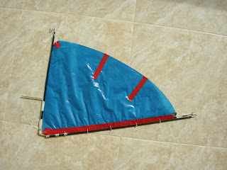
THE RIG:
As previously mentioned, the sail plan was drawn out from the dimensions given in the original plans and the C of E established.


I then bent up a mast support from brass rod which was extended forward to support a luff tube that had been cut a little over length. This was whipped onto the front of the brass rod and the whipping strengthened up with cyno. That part of the rig, the boom and the boat hull was laid over the cardboard template of the sail plan and the whole lot was adjusted until the C of E of the sail led the C of LR (of the fin) by about 1.5cm. Once this was established, the boom was then taped to the brass support tube and in theory, the rig will be balanced, or very nearly balanced on the hull!
The plastic bag that had been earmarked for the sail was laid on the floor and then marked out with the template and cut out, giving the foot of the sail a slight curve for aesthetic reasons…….
A piece of scrap plastic was taken and a strip of electrical tape was stuck to it, a small hole drilled and a piece of whipping twine put through and some tension applied to see whether the tape and the plastic could stand the strain put upon it in respect of sheeting and halyard pulls. A rough and ready assessment established that at least two layers of tape were needed to stop the hole from stretching.
The luff of the sail was overlaid with tape as were the stress point for the clew, the tack and the head. Due to the fact that the sail has a roach built in, when tension was put on the head and the clew, a fold developed in the sail and so it was decided to put a couple of battens in place. A strong but flexible material was needed and eventually I settled on part of a small plastic cable tie that was held in position, again, with a strip of electrical tape.

Two small sections of coat-hanger were inserted into the end of the boom and luff tube and bent to form an anchor point for the halyard and the out-haul.
The Rudder:
Trials with bending up a large paper clip to make up a push rod to operate the rudder from the servo showed that getting the correct length with the necessary bends at each end to stop the whole lot falling apart was very difficult, and so a trip to the model shop came up with several options, including a small barrel nipple which can be fitted to the servo arm and enable the push rod to be easily adjustable.
Rigging the Sail:
The sail was set onto the rig, with the three attachment points temporarily secured and the whole rig was offered up to the very slight breeze and lo and behold, we had some shaping in the sail…………


Sunday 31st October 2010
I screwed the servo tray to its supports and rigged up the rudder servo and battery etc for a try out and think that the small rudder servo may have a fault on it as it is moaning and groaning whilst working, and afterwards, whilst at rest. I may well swop it out for the other heavier duty Futaba servo that came with the Tx kit.
I also started on the second rig and sail and have decided to make this rig from a lighter carbon rod and to change the design of the sail so that it slides onto the front luff tube via a luff pocket (a la Laser!) I am hopeful that this will improve the shape of the sail.


Friday 4th November 2010
Have actually managed to get the rudder push tube sorted with a clevis pin on end of a threaded rod and a “Z” bend in the other. The second hull may well have a clevis pin or “Z” bend and a nipple adjuster - much easier to sort out.
Have had problems with battery access now that the rudder push rod is in position, (I cannot get it in) so have removed the servo trays, cut the ends off and glued the whole lot back in again. I now find that as a bonus, I will have more space for the Rx and it looks as if it should be easier to get to.
The small servo has indeed failed and so I have decided to use both the full sized Futaba servos in both hulls and re-cut the servo trays accordingly.


One of the hulls hit the floor again, and the weight on the end of the fin came flying off and so I have drilled out the weight and pushed a small piece of brass rod with a 90 degree bend at the end, with about an inch shaft that is then going to be pushed up and glued into the end of the fin to try and make a secure joint – araldite is not happy coming together with lead at the moment…….
I offered the deck up to the hull today and found that a little judicious adjustment may be necessary, but was able to mark the position of the mast support tube by just pushing the soft balsa down on the tube and then drilled out the resulting mark.
I have now taken the step of gluing the servo trays into the hulls and also drilled and screwed the servos into their trays. This has now made the whole business of setting the control rod lengths much easier – I should perhaps have done this much earlier on.
I have spent some time trying to work out a method of operating the main-sheet via the second servo without the cordage fouling the servo movement as it slackened off:
I have decided to create a 1:2 pulley to multiply up the movement of the servo e.g. for one inch of movement of the servo arm it will give two inches of movement on the sheet and the majority of the sheeting will be above the deck to try and avoid any fouling of the movements below the deck!
I have used the mast support to secure one end of the sheet and also as a pulley around which the sheet can move. The free end, to multiply up the advantage, will be led direct from the servo arm, through the deck, and onto the other section of the sheet. Dry runs without the deck on will take place!
Once all of this was offered up it was found to work and so I have now made several sets of adjustable sheeting using small wooden “Bowsies” (similar to tent peg tensioners).
To increase the pull of the sheeting system, I have fabricated a “Bridal” to be situated just below the point of attachment on the boom so that the pull of the main-sheet is downwards towards the centre of the hull. This will enable the movement to be equalled up when the sail is on either tack and will also bring the sail more towards the centre line of the hull when sheeted in.
The access hatch has been cut into the deck and the next problem is how to make the cover easily accessible and watertight!
No comments:
Post a Comment